Home / CNC design / Digital example
2.2 m interlocking plywood tree: a digital CAD example
By the Partvo team · October 1, 2026
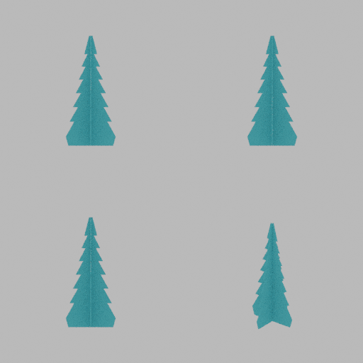
What exists: a two-panel decorative concept with a visible preview and digitally validated STEP, STL and DXF files. What does not: a physical cut, a tested slot fit, a stability approval, a nested sheet layout or machine-ready G-code. The files are downloadable so you can inspect the exact geometry and assumptions.
Download the example files (ZIP, 264 KB)
What are the dimensions?
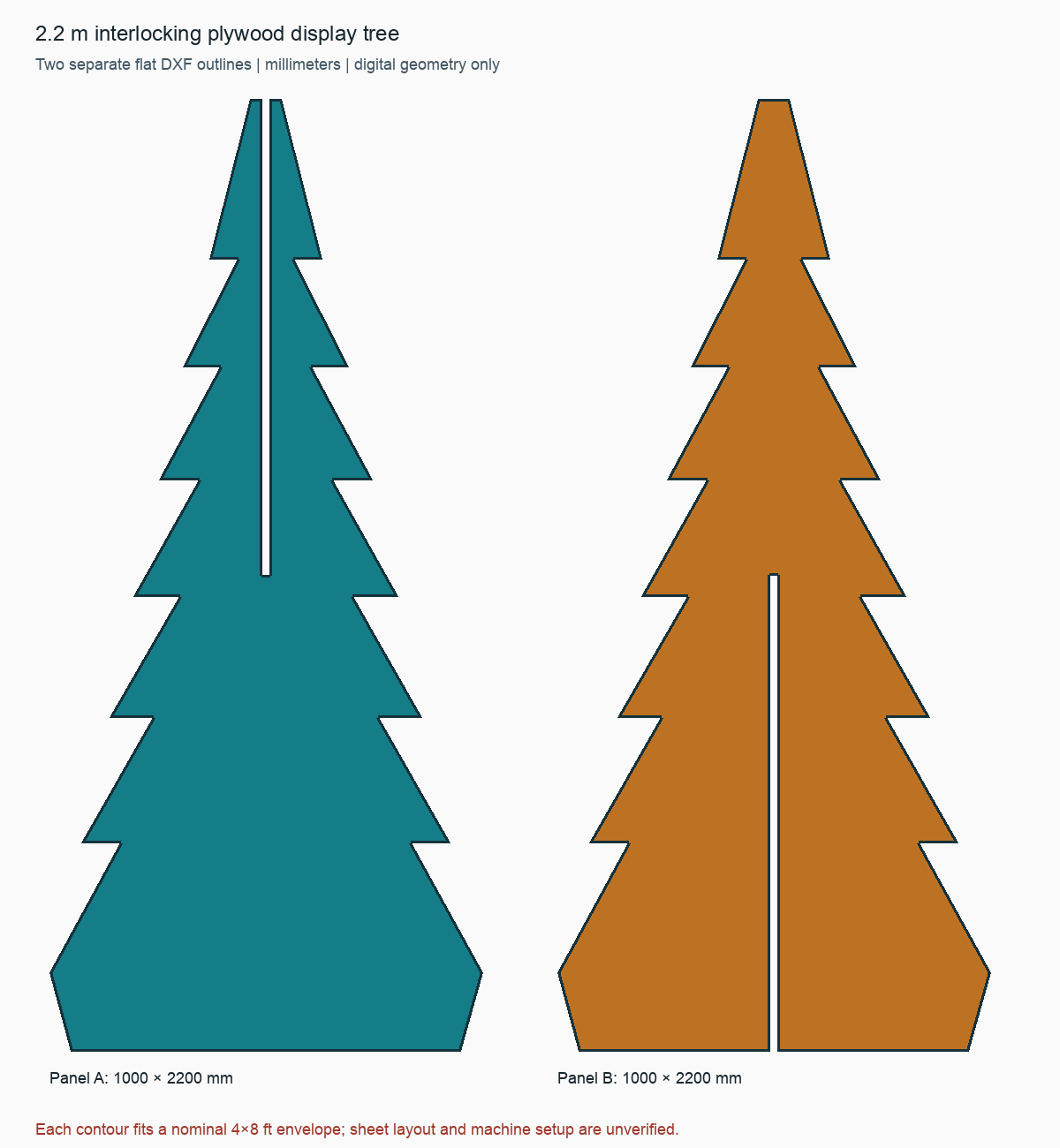
Each flat DXF panel outline measures 1,000 × 2,200 mm. The panels intersect at right angles; the assembled digital reference measures 1,000 × 1,000 × 2,200 mm. One slot opens from the top and the other from the bottom. Both are 18.0 mm wide and extend to the 1,100 mm midpoint. The source assumed 17.4 mm plywood thickness for illustration; no real stock was measured. Each outline fits inside the nominal 1,219.2 × 2,438.4 mm bounds of a 4 × 8 ft sheet, but usable margins, clamps, tabs and nesting have not been planned.
What did Partvo verify?
GPT-6 Sol authored the first build123d source in a local test of Partvo's hosted-program adapter. A human reviewer widened the ground-contact span and adjusted the source for that local test. The exact reviewed source then compiled in Partvo's corrected isolated local CAD pipeline. Its validator reported two watertight solids, a passed STEP roundtrip and two closed DXF contours in millimeters. The app-level bundle validator accepted the ZIP with DXF required. An independent measurement found the two DXF outlines and 18.0 mm slots; a STEP Boolean check measured no overlapping solid volume. These are digital checks only. The validation report explicitly marks physical fit as untested and sheet fit, kerf and toolpath as unevaluated.
Read the machine-readable validation report · Inspect the reviewed CAD source. The complete download also contains the design specification, validation summary and a paired slot-fit coupon DXF. ZIP SHA-256: 95f774d88a40fb85052edd4f1f761bc83e12e50430137f4e0f2de01884e7598b.
What must happen before cutting?
- Choose and measure the actual plywood. Cut the small paired fit coupons with the intended router setup, then measure the resulting slots and try the assembly.
- Have a fabricator add cutter-radius relief or dogbones at the square blind-slot ends, review kerf and fit, then revise the full-size profiles.
- Plan two sheet layouts with real usable margins, holding tabs, cut order and toolpaths in CAD/CAM. The download contains no G-code or machine settings.
- Review an engineered base or anchoring, tip risk and site conditions before installing a 2.2 m tall object.
The source and files are offered as a planning and inspection example, not as cut-tested manufacturing instructions. A local successful example does not guarantee that every comparable request will generate successfully in the live Studio.
How can I ask for a similar design?
Give the full assembly dimensions, each piece's usable sheet bounds, actual material thickness, joint locations and installation constraints. Specify the formats you need and ask the system to flag missing measurements. For example: “Design a two-panel, 2.2 m decorative plywood display for [site]. My usable sheet area is [length × width] and measured stock thickness is [value]. Show separate panel outlines and paired slots, provide a 3D reference and DXF if validation succeeds, and list the fit and stability questions I must resolve with a fabricator.”
Start a measured design
Describe your project in Partvo Studio, then inspect the available files and validation result before using them.
Open Partvo StudioFor the general workflow, read AI CAD for CNC: DXF cutting outlines and manual CAM review.